
Fiber, for when copper runs out of distance.
Single-mode and multi-mode fiber for backbone runs, building-to-building links, and anywhere Cat6A's 100-meter ceiling isn't enough. Routed, spliced or terminated, and tested before handover.
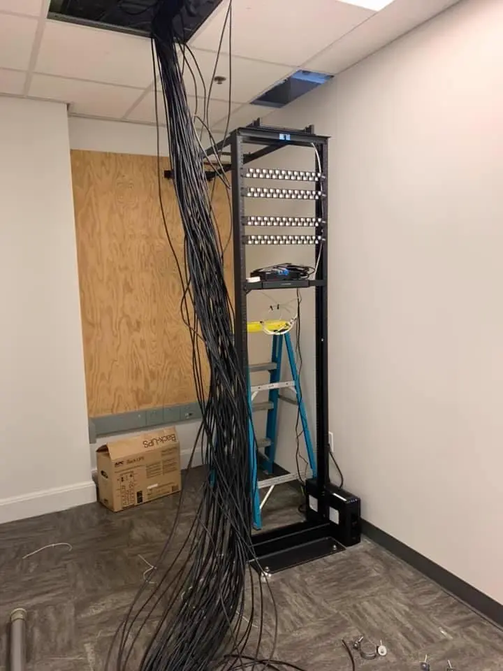
FIBER OPTIC / WHAT IT IS
Light instead of electricity, for the runs copper can't make.
Fiber optic cable carries a signal as pulses of light through a glass core instead of electrical current through copper. That means no distance-driven speed loss the way copper has, no interference from nearby electrical equipment, and reach measured in kilometers instead of meters. It is the backbone that connects racks, floors and separate buildings back to one network.
FIBER OPTIC / WHERE IT SHOWS UP
Satellite centers, operating rooms, cannabis compliance.
Satellite and critical-infrastructure sites where interference-free, high-bandwidth links matter more than the extra cost of glass over copper. Operating rooms and multi-building healthcare campuses where a backbone has to run clean between structures. Cannabis cultivation and retail facilities spread across a site, where security and lab-compliance systems need one network tying separate buildings together. Fiber is what makes that distance a non-issue.
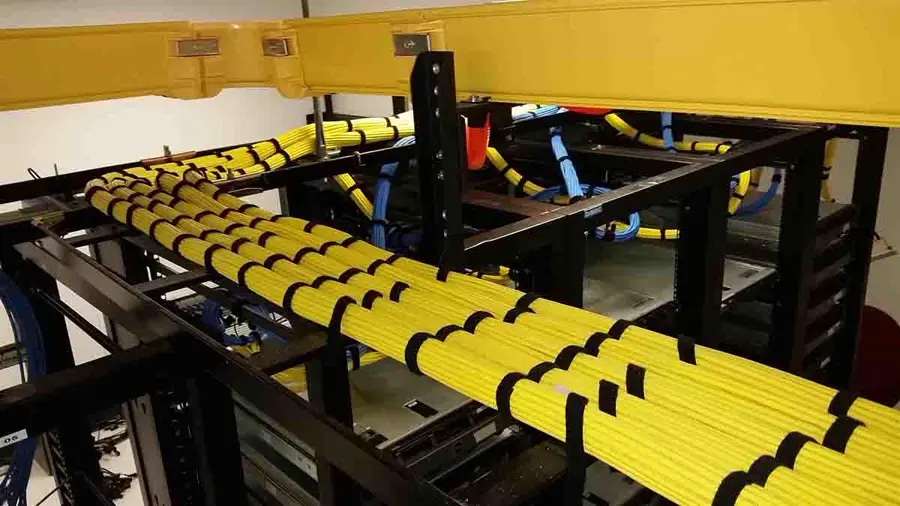
Rack room
Combed, bundled, and routed so the next pull doesn't disturb this one.
FIBER OPTIC / WHY IT MATTERS
Copper runs out of distance. Fiber doesn't.
Cat6A holds 10 Gbps for exactly 100 meters, then the standard stops guaranteeing it. A backbone between two floors, two buildings, or across a large campus routinely needs more reach than that — and fiber is immune to the electrical interference that a long copper run picks up near motors, lighting ballasts and other equipment. It costs more per connection than copper. It is also the only honest answer past a certain distance.
FIBER OPTIC / READ THE LABEL
OM4 or OS2 — here's the actual difference.
Both hold 10 Gbps. The difference is reach and cost per connection. Multi-mode (OM4) is the usual pick for shorter backbone runs inside a building; single-mode (OS2) is the pick for long or building-to-building links.
Ask which one you need →TIA/EIA-568 · fiber carries signal only — powered devices at the far end need local power or a media converter
FIBER OPTIC / WHAT'S INCLUDED
Three things every job includes.
Right fiber for the run
Single-mode for distance, multi-mode for shorter backbone links, decided on the walkthrough by the actual run, not a default.
Spliced & terminated
Connectors and splices finished to the standard the transceiver at each end actually expects.
Tested & certified
A test record for the run before handover — not just a link light on a switch.
FIBER OPTIC / THE PROCESS
From walkthrough to a lit link.
One cable. Five stations. The same process for a two-floor riser or a building-to-building run.
- 01
Walkthrough
We measure the actual run — between racks, floors or buildings — not an estimate off a drawing.
- 02
Design & quote
Single-mode or multi-mode, strand count, route and a written price.
- 03
Install
Fiber pulled and protected on its route, respecting bend-radius limits the whole way.
- 04
Splice & test
Terminated or spliced, then tested for loss before anything is switched over to it.
- 05
Hand over
A labeled record of every strand and its test result.
FIBER OPTIC / DUE DILIGENCE
Before you hire anybody.
Four questions worth asking any fiber bidder, not just us.
- Look up the CCB number.Oregon publishes licence status, bond and insurance for every contractor. Ours is #249201.
- Ask single-mode or multi-mode, and why.The answer should depend on your actual run length and budget, not just what's in the truck that day.
- Ask for a test record, not just "it lit up."A link light tells you almost nothing about signal loss over the run. Ask for the actual test numbers.
- Ask who is doing the splicing.Fiber termination is its own skill. Ask about their experience with it specifically, not just cabling in general.
FIBER OPTIC / WHO CALLS US
We know we are not the only crew on site.
General contractors
Backbone conduit and pathway planned early, before walls close, on multi-building or multi-floor jobs.
IT providers
You own the switches and the transceivers. We get the fiber pulled, spliced or terminated, and tested to spec.
Property & facility managers
One backbone standard tying every building on a campus back to the same network.
LOSS BUDGET
The link is sized in decibels, not feet.
Every fiber run gets a loss budget calculated before a foot of cable is pulled. Start with the fiber's attenuation per kilometer at the wavelength that will run on it, multiply by run length, then add a fixed allowance for every connector pair and every fusion splice in the path. Subtract that total from the difference between the transmitter's output power and the receiver's sensitivity, and what is left is the margin. A design with no margin fails the day someone adds a mid-span splice for a reroute or a connector gets reworked after a bad inspection. The budget also sets the pass/fail line on the final test report — a link isn't accepted because it lights up, it's accepted because its measured loss falls under the number calculated before installation started.
- AttenuationFigured per kilometer at the actual operating wavelength, not a generic number.
- Loss allowanceFixed dB figure assigned per connector pair and per fusion splice.
- MarginTransmitter power minus receiver sensitivity minus the calculated loss.
- RecalculationBudget updated whenever a mid-span splice or extra patch panel gets added.
- Sign-offMeasured result checked against the calculated number, not against "it works."
CONTAMINATION CONTROL
A fingerprint can take down a link.
The single largest cause of fiber failures after installation isn't a bad splice or a broken strand — it's a contaminated connector endface, and it's invisible to the naked eye. A speck of dust sitting on the core scatters light and shows up as unexplained loss or a reflective spike months after handoff. Every connector gets inspected under magnification before it's mated, not just at commissioning, because a clean connector plugged into a dirty bulkhead adapter picks up the contamination on contact. The endface is checked against pass/fail zones drawn around the core, cladding, and adhesive ring — a mark inside the core zone fails even if it looks minor. Dust caps go back on the instant a connector is unmated, and stay on until the next mate.
- Inspection timingBefore every mating, not only during initial installation.
- Pass/fail zonesDrawn separately around the core, cladding, and adhesive ring.
- Cleaning orderDry mechanical method tried first, wet cleaning reserved for stubborn residue.
- Dust capsReplaced immediately on any unmated connector or open adapter port.
- Core zoneA defect there fails regardless of how small it measures.
CABLE CONSTRUCTION
The jacket is chosen for where it runs.
Fiber cable comes built for a specific environment, and picking the wrong construction shows up years later as a failure that's hard to explain. Loose-tube cable, gel-filled or dry water-blocked, is built for outside-plant runs where the fiber floats free of the jacket and temperature swings won't stress it. Tight-buffered cable, where each fiber has its own coating bonded to it, suits the shorter, more heavily handled runs inside a building where it gets patched and repatched at a rack. Interlocking armor goes over cable in direct-bury or rodent-exposed pathways. Jacket rating matters as much as construction — plenum-rated where the run passes through air-handling space, riser-rated for vertical shafts between floors — and outside-plant cable has to transition to an indoor-rated jacket within a limited distance of where it enters the building.
- Loose-tubeGel-filled or dry-blocked, for outside-plant runs exposed to temperature swings.
- Tight-bufferedUsed for shorter, frequently-handled runs inside a building.
- ArmorInterlocking metal added for direct burial or rodent-prone pathways.
- Jacket ratingPlenum or riser, assigned by where the cable physically passes.
- OSP transitionRequired to switch to an indoor-rated jacket near the building entry point.
INSTALLATION MECHANICS
The fiber never feels the pull.
Fiber is pulled by its strength member, never by the fiber itself, and every reel has a maximum pulling tension that a breakaway swivel is set below — if the pull exceeds it, the swivel lets go before the cable does. Bend radius gets tracked in two numbers: a larger radius allowed while the cable is under tension during the pull, and a tighter minimum once it's at rest and unloaded. A cable dragged around a sharp corner or crushed under a cable tie can microbend the fiber inside without breaking the jacket at all — the damage doesn't show on a visual check, only on a loss test. Lubricant gets used on long duct runs to keep friction, and therefore tension, down over distance.
- Pull pointForce applied to the strength member, never transmitted through the glass.
- Breakaway swivelRated below the cable's maximum tension so it lets go first.
- Bend radiusLarger allowance under tension during the pull than at rest afterward.
- MicrobendFrom a crushed jacket or tight cable tie, invisible without a loss test.
- LubricantUsed on long duct runs to hold tension down over distance.
SPLICE ENCLOSURES
Every splice gets a loop, not just a joint.
A fusion splice doesn't just get made and sealed — it gets stored so somebody can get back into it later without pulling new cable. Splice trays stack inside a closure, each one holding a fixed number of splices with the fiber routed in a loop around a radius-limiting comb before it reaches the splice point. Slack is left coiled at both ends of the splice, long enough that a technician can pull the tray out, re-splice a damaged fiber, and put it back without touching the cable outside the closure. Outside-plant closures get gel-sealed or heat-shrunk to stay watertight through re-entry; a closure that's been opened and resealed wrong is a common source of a wet, high-loss splice years after the original work. Every tray gets labeled back to its buffer tube color so a fiber can be traced without reopening every tray in the stack.
- TraysStack inside a closure, each holding a fixed, tracked splice count.
- SlackCoiled at both ends, long enough to re-splice without pulling new cable.
- RoutingAround a radius-limiting comb before the fiber reaches the splice point.
- SealingGel-sealed or heat-shrunk on outside-plant closures to survive water exposure and re-entry.
- LabelingTies each tray back to buffer tube color for tracing without opening every one.
TERMINATION AND RACK BUILD-OUT
The rack end decides what the fiber can carry.
Where the fiber lands in a rack matters as much as how it got there. Adapter panels get populated to match connector type and polish on both ends of the link — a UPC connector forced into an APC adapter doesn't just read as a bad connection, the mismatched ferrule angles can chip the endface on contact, which is why the two are never mated. Inside the rack, slack fiber routes through a radius-limiting spool or drawer rather than coiling loose behind the panel, where it's an easy thing to crush closing the door. Port labeling ties each adapter back to the loss-budget worksheet and the splice tray record on the other end, so a technician troubleshooting years later can trace a single strand from the rack to its origin without re-testing the whole run.
- Adapter panelsMatched for connector type and polish, not just physical fit.
- UPC/APCNever mixed on the same mated pair, since the angle mismatch can chip a ferrule.
- Slack managementRouted through a radius-limiting spool or drawer, not coiled loose.
- Port labelingTies each adapter back to the loss-budget worksheet and splice tray record.
- Cable managersKeep patch cords off the bend radius of neighboring ports.
CERTIFICATION AND DOCUMENTATION
A link is tested in both directions.
Insertion loss isn't the same reading in both directions on a fiber link, so a proper test measures it both ways with a light source and power meter, not once and assumed symmetric. The reference method used to set up that test — how many jumpers and how the meter gets zeroed against them — changes the recorded number enough to matter, and multimode readings depend on the launch conditioning used to fill the fiber's core correctly. None of that belongs in a verbal assurance that the link works. The deliverable is a written report: every fiber's measured loss next to the number calculated in the original budget, a pass or fail against it, and a record kept for the life of the installation so the next technician who touches that link has a baseline instead of a guess.
- DirectionInsertion loss measured both ways, never assumed symmetric.
- Reference methodRecorded as part of the test setup, since it changes the reading.
- Launch conditioningUsed on multimode readings to fill the fiber core correctly.
- ReportingEach fiber's result shown against its calculated budget, not just marked passed.
- RecordsRetained for the life of the link as a troubleshooting baseline.
OUTSIDE PLANT PATHWAYS
Getting between buildings is its own trade.
Fiber that has to leave one building and reach another travels through duct, direct burial, or aerial lashing, and each pathway carries its own rules. A single conduit gets subdivided with color-coded innerduct so a future run has a reserved, already-empty pathway instead of a shared one. Hand holes are placed by pulling-tension distance, not by convenience, so a cable never exceeds its rated pull between access points. Direct-buried cable is rated for the soil it sits in and gets a tracer wire or locate tape run above it so it can be found without digging blind later. Aerial fiber is lashed to a messenger wire with sag calculated for the pole span and the ice and wind load the route will see. Wherever outside-plant cable reaches a building, it has to transition to an indoor-rated jacket within a limited distance of the entry point.
- InnerductColor-coded to reserve separate, empty pathways inside one conduit for future runs.
- Hand holesSpaced by pulling-tension distance, not arbitrary convenience.
- Direct burialPaired with tracer wire or locate tape for future access.
- Aerial lashingSag calculated against pole span and expected ice and wind load.
- Entry transitionRequired to switch to indoor-rated jacket within a set distance of building entry.
FIBER OPTIC / BEFORE YOU CALL
Straight answers.
Do I need fiber, or is copper enough?
Copper (Cat6A) is rated for 10 Gbps up to 100 meters. Past that distance, or between separate buildings, fiber is what carries the signal without losing speed. We measure the actual run on the walkthrough rather than guessing.
Single-mode or multi-mode — what's the difference?
Multi-mode fiber (OM4) is rated for 10 Gbps up to about 400 meters and is typically less expensive per connection. Single-mode fiber (OS2) holds 10 Gbps out to roughly 10 kilometers. Short backbone links usually use OM4; long or building-to-building runs usually use OS2.
Can fiber power a camera or access panel the way PoE copper does?
No — fiber carries signal, not power. A device at the far end of a fiber run needs its own power source or a media converter that also injects power locally. We plan for that on the walkthrough, not after the fiber is already in the wall.
Do you splice and terminate fiber yourselves?
Yes, that's part of the same job as the pull — routed, spliced or terminated, and tested before handover.
Are you licensed for this work?
We hold Oregon CCB #249201, Oregon electrical licence 4911LEA, CLE723 and Washington licence KNEPPJK854KK, with $2,000,000 in liability insurance and a $50,000 bond.
How do I get a quote?
Book a walkthrough. We look at the building, then you get a written scope and price you can compare against anyone else's.
FIBER OPTIC / NEXT STEP
Light, where copper runs out.
Tell us the run — between racks, floors or buildings. We'll come measure it.
Move the pointer across this band